Most of us will have the need for a nice drink after a hard week at the office once in a while and some of us will choose to make ourselves a cocktail, or go out and have somebody make one for us. This cocktail will give us some relaxation, but it can also spark our engineering brain. How is this cocktail mixed, what type of booze is in it and how does that relate to the dimensions of the glass it is in and can I streamline the process of making a cocktail. Well a while back @Autodesk made this tweet:
Which was about a CAD file that is known as “The Engineers Guide to Drinks” which is a drawing of different drink in the way an engineer would make the drawing. Different hatches, symbols for various things. It looks very nice and has the feel of a construction drawing.
I had seen the file before and thought is was pretty cool then and still did this time, but wanted to know a bit more. So, I ended up at the blog ‘Between the Lines‘ by Shaan Hurley. He was the one that did the CAD drawing based on a drawing made in 1972. Over the years there have been multiple changes to the file. One that is very cool is an old hand drawn one from 1974 which is in the US National Archives for some reason. Find out it’s story here.

Cocktail construction file found in the US National Archives.
On his blog Shaan set the challenge (well that’s how I see it anyway) to make the file in other CAD programs, Revit being one of them, and that triggered me to give it a go, thinking it should not be that hard.
First try
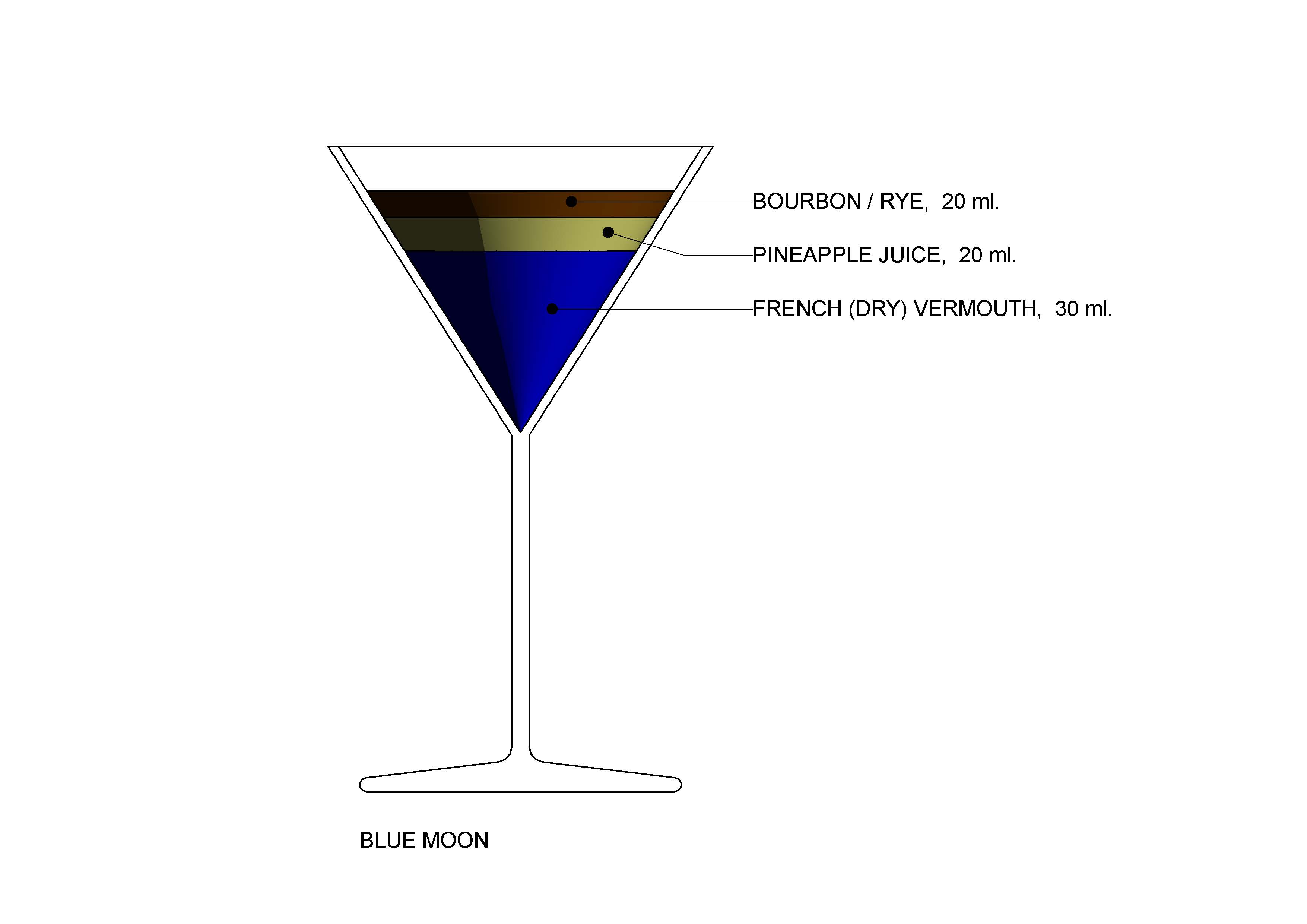
The first task was going to be the cocktail glass, nice cone shaped, with simple dimensions. So I looked up the size of a cocktail glass and modeled that in Revit, which was an easy task. Needed to fiddle a bit with it to get both the dimensions and volume right, but in half an hour or so the glass was there. Next task was to fill the glass with booze, started off with 3 layers and used trial and error to get the the right volumes and the glass looks pretty nice.

I figured out the height of different volumes of liquid and I could change the volumes pretty quick. But then it hit me, “This is not a very Revit like way of doing thing my friend”. Figuring out the height of the liquids by trial and error might be OK for that one glass, but I was not going to do that one glass, I needed to make a lot of cocktails according to the previous attempts, so I was going to do this the Revit way and parameter the hell out of the glass. Well, that sure sounded a lot easier in my mind then how it turned out in the end.
The formula
Being 36 myself and out of school for 16 years or so and never really needing to do things like this before I had to think really hard about what to do. I needed the height of the liquid level for each layer and I knew the angle of the glass and the volume of the liquid (I knew that the cocktail had for example 10, 20 and 30 ml of liquid in it). So how to calculate the height in the glass? I tried a lot of different ways, looked all over the internet and even asked colleagues to help me out and we could not solve it. Finally asked another colleague and he said that his son would probably solve it in 5 minutes. I thought, “sure he will”, but can’t hurt to let him try. That night I got a message telling me he indeed solved it in a few minutes and a photo of the calculations he made.
Going over the calculations they kinda made sense to me, but I also realized I could never have gotten to that solution myself, so I’m very happy with the help I got.
This is the simple looking formula I am using for the calculations:
b = height of liquid in the glass
V = volume of added liquid
h = total height of the glass
r = radius of the top of the glass
Getting it in Revit
I now had the right formula, checked it against my trial and error approach and it worked! Now to get that thing into my Revit family. This gave me a new set of challenges of course, as there are things in that formula you do not really use on a regular bases in Revit, how to do the cubic root thing for example. This is where the great Revit Forum helped me out. In the thread Revit Formulas for “everyday” usage I found the solution:

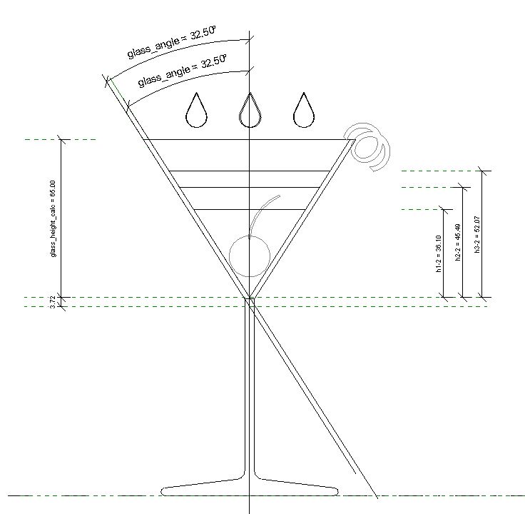
At this point I had all the data I needed to build the glass with parameters, so started with the glass I already modeled and added the needed ref planes, ref lines and dimensions to be able to control the height and angle of the glass.
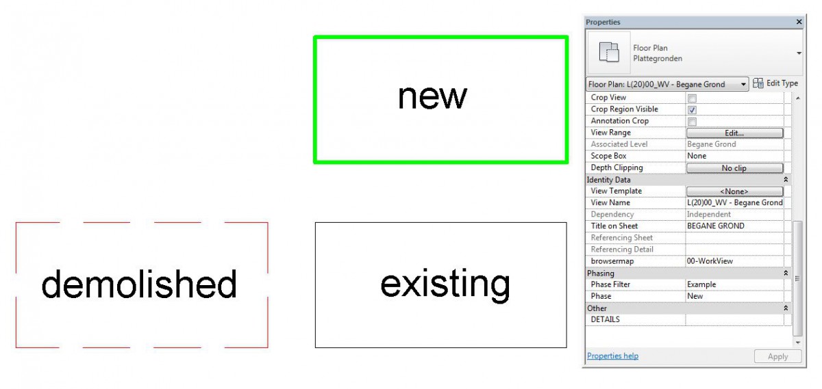
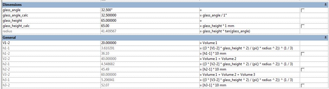
Then all the needed parameters and formulas. I have chosen to convert all my parameters to ones without units to avoid the Inconsistent Units popup in Revit. Pretty sure that is not needed and I might change that in the end, but for now removing them and at the end adding them again works well for me. As you can see from the drawing above and the parameters below I have chosen to calculate each height from the bottom of the glass instead of doing one layer at a time. This means I have to add the previous layers of liquid to the next one in order to get the total height.
Polished the family a bit and I am pretty happy so far. Still needs some work, but good enough to add it as a download
Download: http://www.deurloo.net/download/3229/
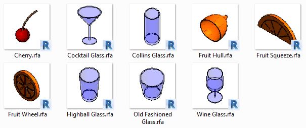
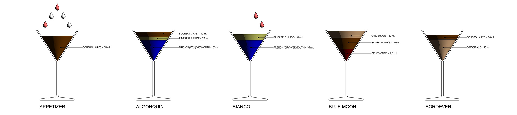
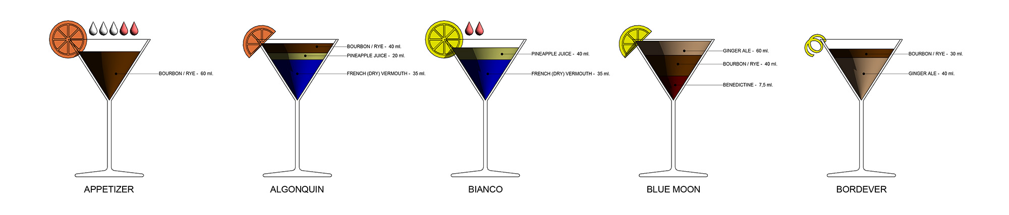
Now what?
As you can see at the top of this post, there are a few more glasses to be build and there needs to be a project made with all the glasses and materials in it, so we can build each cocktail we want. So, if you want to help out in any way, let me know with the reply form below, the contact form on this website, Twitter, Facebook, LinkedIn, engineersguidetodrinks@deurloo.net or on the Revit Forum and we’ll figure out who can do what.
But should we stop with Revit, can we BIM this thing??
Next Post: The Engineers Guide to Drinks – Continued